Motor Controller Selection for Outdoor Wheeled Robot Drivetrains
Terrain, not motor specs, determines whether outdoor robot controllers survive extended operation.
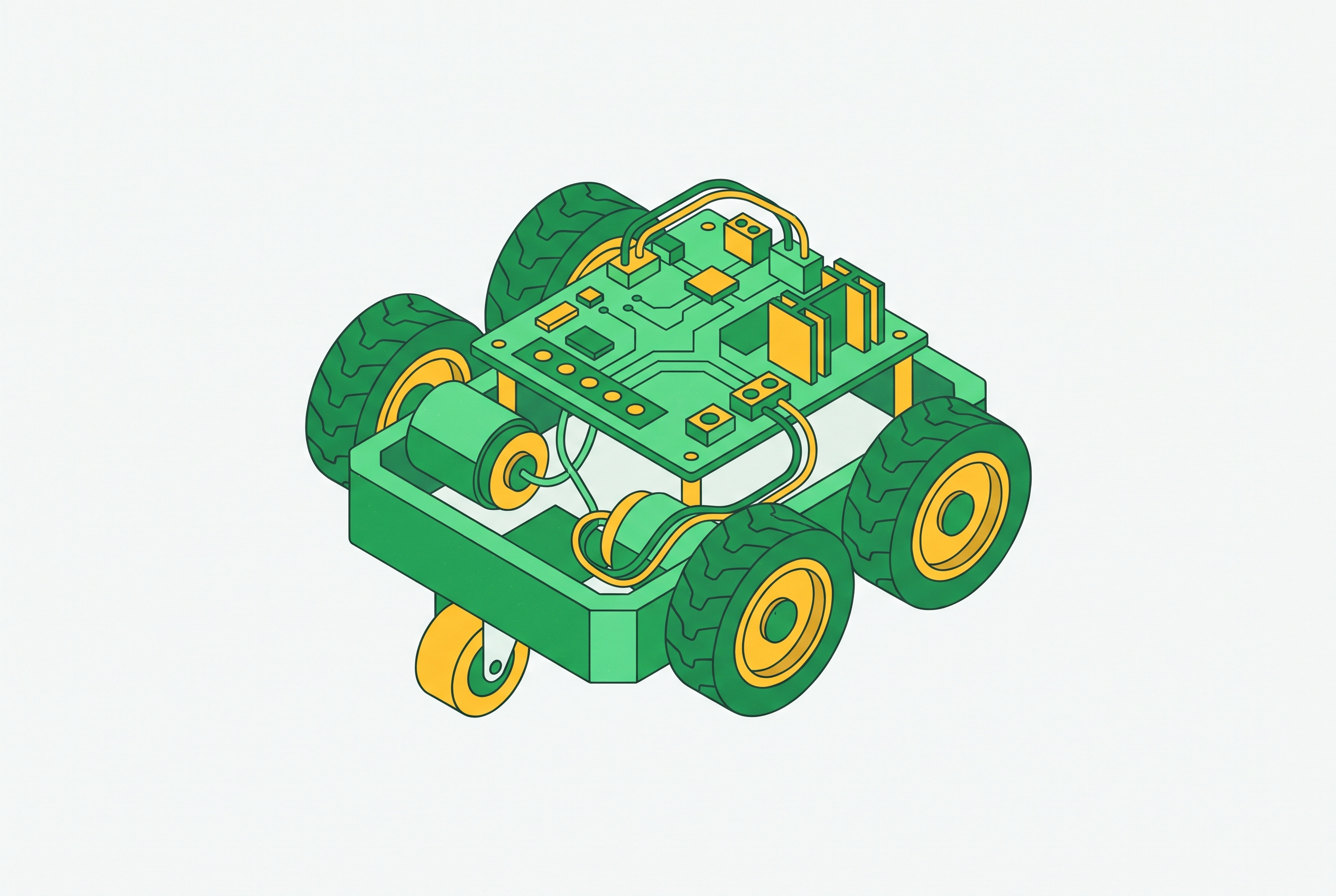
The controller that works flawlessly on a bench and smoothly through a warehouse aisle begins to falter the first time the robot climbs a gravel slope for twenty minutes. The failure is rarely catastrophic. It is a quiet degradation: torque falls off, speed sags, and the platform that met every specification starts missing its cycle time.
The cause is not a defective component but a selection made against the wrong reference. Controllers chosen from motor datasheets alone are sized for a world that does not exist outdoors. This piece walks through the physical reasoning that connects terrain to controller constraints, and then through the specific decisions that follow from it.
Why outdoor drivetrains punish controllers selected from motor specs alone
A prototype that performs well on flat ground at rated payload will often begin limiting output on a modest incline after extended operation. This is not a component failure. It is a system mismatch between thermal reality and what the controller was rated to handle. The controller was never asked, at selection time, what the terrain would demand of it.
Outdoor duty cycles add stop-and-go acceleration, gradient transitions, and variable surface resistance. None of these appear in a bench test or a motor catalogue. The motor's power figure holds roughly constant across the catalogue page, but the current it actually draws changes dramatically with every degree of grade and every shift in surface.
The deeper problem is procedural. The controller is typically selected last, after motor, battery, and wheel geometry are already fixed. By that point, its sizing is constrained by decisions that were never evaluated against real terrain loads. The controller becomes a derived quantity rather than a design input, and the field becomes the place where that ordering fails.
Yet the same motor that stalls on a hill in service would have shown no sign of trouble under the conditions used to select it. The datasheet does not misrepresent the motor. It simply omits the environment in which the motor will live.
How outdoor terrain turns drivetrain physics into controller constraints
The wheel torque the terrain demands, not the motor's rated power, is the correct starting point for sizing a controller. Power is easy to compare across datasheets, but wheel torque is what actually determines whether the robot moves under real load conditions. The two figures answer different questions, and outdoors the second question is the one that matters.
Working backwards from required wheel torque, the total force on the robot must overcome rolling resistance, gradient load, and acceleration demand all at once. A smooth warehouse floor puts almost the entire burden on acceleration. A muddy field raises rolling resistance until it dominates. These are not subtle differences. They change the current envelope by measurable multiples.
Wheel diameter quietly changes every downstream calculation. The same motor current produces less forward force because the lever arm has grown. That shifts the required current envelope the controller must handle, and no motor datasheet will surface the interaction.
Incline transitions are the highest-stress event, and they are ordinary outdoors. A modest grade sustained over an extended shift forces the motor toward its current limit far longer than any momentary peak. This sustained condition, not the stall event everyone designs for, is what exposes controller thermal margin.
Battery operation adds a second coupling to all of this. As the battery discharges, bus voltage sags, and the controller must draw more current for the same torque output. The terrain did not change. The system did.
The four parameters that govern every valid controller selection
A valid controller selection requires satisfying four coupled criteria simultaneously. Meeting any three while missing one produces a system that fails in the field. The criteria are not independent. They are four views of the same underlying question: can this controller sustain the actual operating current, at the actual operating voltage, with the actual thermal behavior, under the actual control demands, for the full shift?
The first parameter is voltage match. The controller must operate within the motor's correct voltage range. Selecting the highest practical DC bus voltage reduces operating current and losses across the whole drivetrain, but the controller must tolerate the full range that the battery will actually present, from fully charged to near-depleted, under load and during regeneration.
The second parameter is the relationship between continuous and peak current. The goal is that the continuous rating, not just the peak, covers real operating current. Peak ratings sell controllers, but continuous ratings determine whether the robot completes a shift.
The third parameter is I²t thermal protection. Both motor windings and controller FETs tolerate brief overcurrent but not sustained current. I²t protection models accumulated heat by allowing elevated current for short acceleration windows, then folding back to the continuous rating. Configurable continuous and peak current limits that approximate this thermal envelope are a feature to verify in any candidate controller.
The fourth parameter is communication interface and control mode. Vector control, field-oriented control or FOC, enables accurate torque control across the full speed range including zero speed, and the distinction matters for outdoor platforms that start under load. The interface must match what the robot's computing stack can drive: CAN, CAN-FD, UART, and RS485 are common. A mismatch here is a system integration failure, not a component failure, and it is as fatal to the deployment as an undersized continuous rating.
Continuous torque, thermal margin, and the duty cycle the controller actually sees
The thermal condition the controller reaches after hours of operation, not the peak current at startup, is what determines whether the drivetrain completes its mission. Early prototype testing looks favorable because windings are cool and the battery is fully charged. The controller's true thermal margin only becomes visible after extended operation under load.
An outdoor AGV or field robot spends most of its operating time at a steady cruising current, not at stall. The DC bus and controller thermal design should be sized to the real duty cycle, not the peak. A designer who sizes to stall current is engineering for a condition the robot almost never occupies, and ignoring the condition it occupies continuously.
Thermal throttling is not a failure mode. It is a design signal. The throttling behavior is often blamed on the controller or the motor or the battery. It is properly blamed on the selection process that produced all three.
Oversizing the motor does not solve this, and can worsen it. Those changes increase thermal load on the battery and bus during acceleration rather than reducing it. The instinct to solve a thermal problem by buying a bigger motor commits the same error as sizing the controller to peak current: it treats a sustained-condition problem as if it were a capacity problem.
Brushed vs. brushless for outdoor duty: where the trade-off actually falls
For most outdoor wheeled drivetrains, brushless motors with sensored controllers are the better system choice. But the case for brushed is real in specific conditions and should not be dismissed out of hand. The recommendation defaults to brushless for reasons that are easy to articulate. The exceptions are narrower but no less legitimate.
The efficiency gap matters for battery operation. Brushed DC motors run at lower efficiency than BLDC motors, and on a battery-powered outdoor platform that gap translates directly into shorter run time or more frequent charging. A few percentage points of motor efficiency compounds across an eight-hour shift into a real operational difference.
Outdoor environments specifically degrade brushed systems. Moisture and corrosion attack brush and commutator surfaces. Sealed brushless motors are structurally better suited to the environment, and the absence of wearing contacts removes a failure mode that humidity, condensation, and temperature cycling actively accelerate.
The honest case for brushed rests on two grounds. In dusty, contaminated, or rough-handling environments where electronics are the vulnerability, the simpler system survives longer. A brushed drivetrain with a two-channel controller can be built, repaired, and understood by a technician with a multimeter and patience.
FOC is the emerging commutation standard on the brushless side. Field-oriented control enables accurate torque control and greater motor efficiency across the full speed range, including full torque at zero speed. That capability is critical for smooth starts under outdoor load conditions, where a robot beginning to climb from a standstill on an incline needs controllable low-speed torque rather than a jerky open-loop start.
Single-axis vs. multi-axis controller architecture for multi-wheel outdoor bases
Multi-wheel outdoor drivetrains require an explicit architectural decision about whether to distribute controllers per wheel or centralize them. The right answer depends on specific operational priorities, and neither approach dominates until the operational context is defined. One controller per wheel is modular. The architecture scales to any wheel count without re-architecting the control topology. The costs are real: synchronization must happen over a shared bus, and the harness grows more complex with every additional node.
A single multi-axis controller offers tight built-in synchronization between channels, which matters for differential drive where speed matching is critical to straight-line travel. Fewer parts, simpler harness, and a single configuration interface are genuine advantages during both build and maintenance. The trade-offs are equally concrete: a single point of failure for the entire drivetrain, a fixed axis count that constrains future design changes, and concentrated heat in one unit during sustained outdoor operation.
The outdoor-specific consideration cuts differently depending on what the deployment values. A robot whose harness will run through hostile terrain benefits from fewer conductors and fewer points of failure. The decision must be made explicitly, against those conditions.
How specific controller platforms handle outdoor drivetrain requirements
Each major controller platform makes a different set of trade-offs across the selection criteria. Matching those trade-offs to the outdoor duty cycle is the practical application of the framework, and the platforms below are best read not as a ranked list but as a map of how different priorities resolve into different hardware choices. The RoboClaw 2x60A from BasicMicro is a brushed, two-channel controller with continuous and peak current ratings per channel. It incorporates temperature, current, over-voltage, and under-voltage protection that is self-monitoring under operating conditions. Its practical fit is outdoor brushed drivetrains requiring dual-channel control, regenerative braking on slopes, and self-monitoring protection without external configuration. The ODrive Pro delivers high continuous and peak power output across a wide voltage range, with isolated CAN, UART, Step/Dir, and PWM interfaces plus isolated GPIOs. Its practical fit is brushless outdoor drivetrains requiring FOC performance and fieldbus connectivity in a two-wheel architecture.
The VESC line, including the VESC-LS series, generally provides more sophisticated regenerative braking options, including configurable brake curves and energy recovery optimization. That sophistication is relevant for outdoor platforms operating on grades, where the difference between basic and configurable regen shows up in both energy recovery and hill-descent control. Its practical fit is heavier outdoor platforms where regenerative braking configuration and open-source firmware customization are priorities.
The MJbots Moteus r4 integrates 3-phase brushless FOC for BLDC motors with an STM32G4 microcontroller, an absolute magnetic encoder on-board, and a 5 Mbps CAN-FD interface. It supports position, torque, and velocity control modes, and the on-board absolute encoder eliminates a separate component. Its practical fit is brushless outdoor drivetrains requiring CAN-FD, FOC, and compact integration.
The Roboteq GBL family is designed for precise speed, torque, and position control in single or dual-channel architecture, supporting both 6-step trapezoidal and 512-step sinusoidal FOC commutation. It features battery operation support, regenerative braking, fieldbus connectivity, rugged construction, and Functional Safety with Safe Torque Off. Its practical fit is outdoor platforms with industrial-grade requirements, Functional Safety certification needs, or demanding fieldbus integration.
Integrated motor-driver-encoder modules and what they change about the selection process
Integrated motor-driver-encoder modules collapse the component boundaries that the selection framework assumes. The traditional process treats motor, controller, and encoder as three separate components matched to each other. Integrated modules remove at least one layer of that matching problem, and the simplification is real.
The DFRobot M0601 Hub Motor collapses all three into one unit with a shared IP54 rating. The M0601 is driven by FOC algorithms and a 4096-line high-precision encoder, achieves triple-loop closed control across torque, speed, and position, and carries a 2.0 N·m stall torque. The integration means the encoder is inherently matched to the controller's commutation requirements. That matching is no longer a separate engineering task.
What the integration changes is the scope of the selection decision. But the integrated module's fixed specifications, its current rating, voltage range, and thermal design, must still be verified against the real outdoor duty cycle using the same criteria. The framework applies. The component boundary does not.
What the integration does not solve is the thermal constraint itself. If the module's continuous current rating is undersized for the terrain, integration does not change the outcome. The thermal constraint is the same whether the components are separate or combined, and a unified enclosure with a shared thermal path is no substitute for a continuous rating that covers the sustained current the grade imposes.
Applying the framework: sizing a controller to an outdoor duty cycle rather than a motor spec
Selecting a controller for an outdoor wheeled robot drivetrain is not a lookup exercise but a sizing exercise. It must begin with terrain conditions and work backwards to component ratings. The sequence matters because each step constrains the next.
The first step is to define the operating environment before touching a catalogue. Total operating mass and payload, maximum expected grade, surface type and rolling resistance, target speed, and daily operating cycle all need to be fixed. That last item must include not just peak moments but the sustained condition the robot spends most of its time in.
The second step is to derive wheel torque under the most demanding realistic condition. That is not average load and not peak stall, but the highest sustained load the terrain can impose. This figure determines real operating current, and it is the one that matters for everything downstream.
The third step is to size the controller to that sustained current, not to motor peak. Confirm that the controller's continuous rating covers the expected sustained current. Verify that thermal protection, I²t or equivalent, allows short overcurrent for starts without requiring a continuous rating large enough to accommodate stall current indefinitely.
The fourth step is to verify that the battery can continuously support expected current. Bus voltage under load, not nominal voltage, determines whether the controller's protection thresholds will trip during the duty cycle. Regenerative braking capability should be confirmed against the grade profile, not treated as a bonus feature.
The fifth step is to confirm that the interface and architecture fit the compute stack and wheel count. Communication interface compatibility and the single-axis versus multi-axis decision should be resolved at this stage, after the electrical sizing is fixed. Architecture is a consequence of electrical reality, not a starting assumption.
The system-first principle holds all of this together. The terrain is the specification. Everything else is a response to it.
Sources
- TurtleRabbit 2024 SSL Team Description Paper
Referenced in the article as the source associated with the MJbots Moteus r4 controller description, which integrates FOC, CAN-FD, and an on-board absolute encoder.
- Brushless Servo Motor vs. Brushed Motor
Informed the comparison between brushed and brushless motors, particularly the efficiency gap and suitability of brushless motors for outdoor environments.